
Saturday, January 30, 2010


Sunday, January 10, 2010
Fabricating Light - pixel field rendering

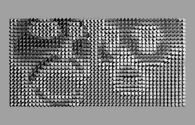
Attached are two images showing the assembly with the updated image. The first shows the pixels rotated in relation to the lighting source, the second shows the same pixels with the light source on the other side of the room, if we were to put two contrasting lights on it and switch between the two.
We're considering using two projectors for the lighting since they can be mounted where we need them and then we can set up black/white movies to play and the light will switch between the two. Since we can basically create the lighting effects however we want in aftereffects, we'll have a lot of freedom to do our own on-off transitions between the two projectors.
We chose to use a more figurative image as opposed to the previous one which was more abstract. We felt that since the main thrust of the project was to convey how the light is creating the image on the board, that might be lost if the image is something that becomes simply a texture of rotated pixels. By creating a more recognizable image, the viewer isn't trying to discern the image and can focus on how the system functions.
This demonstration in its current iteration functions as static representation of a responsive system. The individual pixels respond to the external stimuli of a singular light source, each altering the orientation of its base and angle of its face according to the intensity of illumination that it receives. Acting in concert, the pixels depict the image of two Native American masks from the Pacific Northwest. While the pedigree is inconsequential, the mask is pertinent to the overarching concept behind the system. The mask represents a crystallization of the human face in a specific moment in time. Composed of a complex network of nerves and musculature, the human face is perhaps the most evolved responsive topological system occurring in nature as it constantly adapts to changing environmental and emotional stimuli. It is the interface through which all human interaction is conducted. Depending upon the stimuli, the face responds accordingly and produces the desired result. Likewise, the pixels respond to the light source to generate the image.
Friday, January 8, 2010


Tuesday, December 1, 2009
Tuesday, October 27, 2009


Wednesday, October 21, 2009
Solidworks Perf Panel Tutorial 04 FEA
This Solidworks tutorial covers (approx. 25 min):
1. How to produce a Flat Pattern for folding and fabrication
2. How to create the support base needed for testing
3. Introduction to Finite Element Analysis (FEA)

Sunday, October 18, 2009


Friday, October 16, 2009


Thursday, October 15, 2009


Solidworks FEA Tutorial 01

Please visit this web site: http://www.solidworksmedia.com/SimulationXpress/index.html
Here you will find a thorough video tutorial on how to use SimulationXpress to produce a FEA study of your part. SimulationXpress allows for quick and accurate FEA studies but is limited in it's scope of analysis. Please take a look at this tutorial and we will discuss how to apply this to your sheet metal parts in class.
5x5 borges, bunt, lee, white


manually set the z axis 1/2" high during the pocket hole run in order to prevent cutting through as happened with the test pixels, then reset at 0 for profile cuts
adaptation worked, for the most part, except where bowing of the plywood caused the material to sit too high at some cuts.
other learning from failures...
*we did not take into account the difference in orientation of cut for the pockets and tabs. pockets have rounded edges, tabs have square edges. so...square peg, round hole. this required a touch of sanding and/or forcing in assembly.
* plywood is bad for small/intricate pieces (especially the cheap stuff). it tends to separate at the laminations, counter to the actual depth of a pass, making breaks and jagged cuts.
* extra pieces = good
* we had issues with the material bowing and raising on the profile cuts as well. because we didn't place drill holes in the mastercam file, interior support screws were done ad hoc, during the milling process. not ideal.
Subscribe to:
Posts (Atom)